7. 3D work#
Everything so far has cut 2D geometry to a depth. 3D Profile is different: it follows a surface, taking its shape from an imported STL mesh and sweeping a round-nosed cutter back and forth across it until the wood matches the model.
This is how you carve a relief — a sign with a raised crest, a topographic map, a face, anything modelled elsewhere.
Importing an STL#
Import File in the toolbar takes .stl in both binary and ASCII form. Drag-and-drop
onto the canvas works too.
What appears on the canvas is a rectangle, not a mesh — the model's XY footprint at its true size, placed in the middle of the stock. The mesh itself rides along with that rectangle; the rectangle is the handle you use to place and size the carve.
Switch to the 3D View to see the actual model.
Placing and sizing it#
Move and scale the rectangle like any other object (chapter 2). Two things about how that maps onto the carve:
The top of the model becomes the top of the stock. The mesh's highest point is placed at Z 0 and everything else hangs below it, so the whole relief cuts into the board. You don't position it in Z; you decide how deep you'll let it go.
Depth scales with the average of the X and Y scaling. Scale the rectangle uniformly and the relief keeps its proportions — twice as wide is twice as deep. Scale it non-uniformly and the height is scaled by the mean of the two, which will not match either axis, so a stretched model is a distorted one. If you care about the proportions, scale uniformly.
An STL is a surface, and this operation carves it from directly above. Undercuts — anything that overhangs itself — cannot be machined on three axes, and the carve simply takes the highest surface at each point. Model accordingly.
The 3D Profile operation#
Select the STL's rectangle and choose 3D Profile. The form has two halves.
Finishing — the pass that makes the surface#
| Field | What it does |
|---|---|
| Tool | Ball nose or taper only. A flat cutter cannot follow a curved surface |
| Stepover (XY) | Spacing between passes, as a percentage of tool diameter |
| Angle | Which way the raster lines run, −90° to +90° |
| Max Depth | How far below the stock top the cut may go |
Stepover is the finish quality control, and it is the expensive one. The cutter is round, so between two adjacent passes it leaves a ridge — a scallop. Halving the stepover halves the scallop height and doubles the number of passes, and 3D finishing passes are long to begin with. A small ball nose at a fine stepover can run for hours.
On a taper, stepover is a percentage of the tip, not of the cutting diameter. A 30% stepover on a 2 mm tip is 0.6 mm — the form spells the millimetres out beside the percentage, which is the number to judge.
Pick the angle to run the passes along the length of the detail rather than across it — a face reads better rastered vertically, a long ridge along its own axis.
Roughing — the pass that saves the finishing cutter#
Optional but almost always worth it. Without it, the finishing tool has to remove everything, taking full-depth cuts with a small round bit — slow, and hard on the cutter.
| Field | What it does |
|---|---|
| Roughing tool | A ball nose, usually a bigger one. None gives a single-pass job |
| Roughing stepover | Wider than the finishing stepover — this pass is for volume, not finish |
| Roughing step down | Axial depth per level |
| Roughing angle | Defaults to 90° from the finishing angle, so the finish pass crosses the roughing marks |
| Stock allowance | Material left for the finishing pass — 0.3 mm by default |
The finishing pass is rest-machined: it knows what roughing already removed and only cuts what's left, so it doesn't waste time cutting air over ground that's already clear.
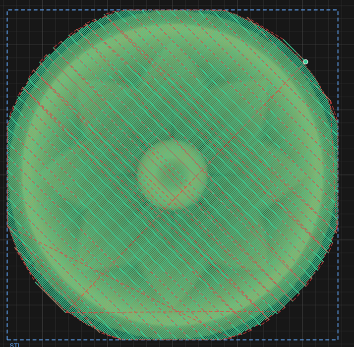
Both passes drawn together. Finishing is set to 45°, so roughing defaults to 135° and the two cross at a right angle — finishing across the roughing grooves cuts a more even chip than following them.
Checking it#
The 3D View is not optional on this kind of job. A relief has no outline to sanity-check on the 2D canvas; the toolpath is thousands of near-identical passes and reading it tells you nothing.
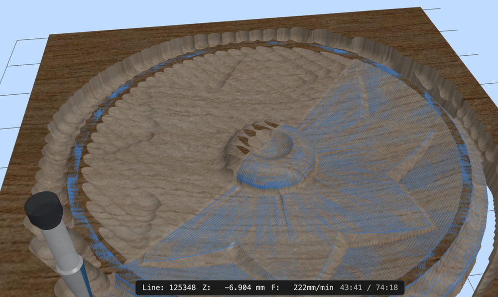
Part way through a relief. The ridges around the rim are roughing scallops the finishing pass hasn't reached yet — and the clock says 43:41 of 74:18.
Simulate, then look at the carved surface. What you are checking for:
- Scalloping you can see in the render will be there in the wood.
- Flat spots where the tool was too big to reach into a hollow. A ball nose cannot cut a valley tighter than its own radius, and the simulation shows exactly that.
- A relief that bottoms out, meaning Max Depth clipped the model rather than the model fitting the board.
And check the estimated run time in the export review before committing. 3D finishing is where a job quietly turns into an overnight one.
Next#
- 8. Parametric parts — gears, clocks, track and cutting boards
- 10. Simulating and exporting — the review before you cut